At Zimmer and Peacock we help our clients in the development and manufacturing of medical diagnostics and biosensors for their applications, programmes and products.
Sometimes the client is trying to both develop the reader electronics and the sensor in parallel, which can lead to problems when there is an issue with the sensors and/or the electronics; in this situation the client is left wondering 'is it my electronics, or is it my sensor?'
A useful strategy when developing an electrochemical biosensor or medical diagnostic is to decouple the electronics development from the biosensor development, as too many dependencies between the two programmes can lead to confusion.
Zimmer and Peacock help their clients during the electrochemical sensor development by providing validation sensors. Our validation sensors have exactly the same form factor as our standard sensors and will give a signal output that is equivalent to the biosensor/sensor/medical diagnostic except the device is entirely solid state, i.e the device has a number of capacitors, resistors, diodes etc, in a parallel and/or series circuit which will give a response which is equivalent to the sensor under development.
The principle of using these equivalent circuits is well known in electrochemistry but Zimmer and Peacock goes beyond best standard practise and manufacture standard equivalent circuits in exactly the same format as our standard sensor, so the engineer can be certain that the results from this equivalent circuit are applicable.

The validation sensors from Zimmer and Peacock are exactly equivalent to biosensors/sensors/medical diagnostics but the use of solid state components means the engineers doesn't have to be burdened with wet reagents etc, when testing electronics etc.


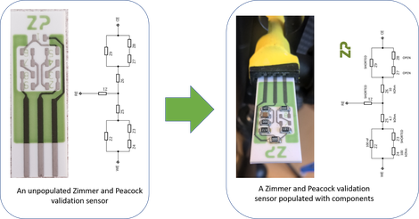
In the adjacent image the Zimmer and Peacock engineer has populated a bare validation sensor with solid state components that define an equivalent circuit of the sensor of interest.
In the images below we have taken a standard Zimmer and Peacock validation sensor and run it on the Ana Pot EIS. The test circuit was tested using electrochemical impedance spectroscopy, potentiostatic mode, galvanostatic mode and cyclic voltammetry.


If you have any questions regarding the use of validation circuits in sensor development please feel free to contact us.